How to Fix LoRaWAN Gateway Packet Loss: Antenna and Cable Optimization Guide
How to Fix LoRaWAN Gateway Packet Loss: Antenna and Cable Optimization Guide
Deploying an enterprise LoRaWAN network promises exceptional range and deep building penetration. However, many network administrators face a critical issue during scaling: unexpected packet loss (high Packet Error Rate). While software configurations and network server adjustments are often blamed, more than 70% of packet drops in industrial LoRa IoT nodes are directly rooted in physical Layer 1 RF degradation—specifically, sub-optimal antenna placements, high insertion loss from improper feedlines, and impedance mismatches.
Because LoRa systems operate over unlicensed Sub-GHz ISM bands (such as US915 in North America and EU868 in Europe), managing link budget efficiency is non-negotiable. To ensure reliable communication, systems must adhere to strict hardware deployment criteria to prevent weak uplink reception.
1. Antenna Elevation & Clearing the Fresnel Zone
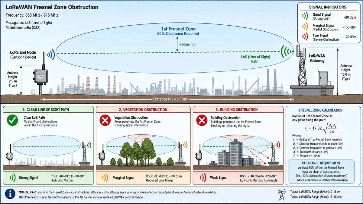
The first rule of eliminating LoRaWAN packet loss is overcoming structural line-of-sight (LoS) blockages. According to the deployment frameworks set by The Things Network (TTN) Gateway Placement Best Practices, a LoRa gateway antenna must be positioned as high as physically possible to keep the Fresnel Zone clear.
The Fresnel Zone is the elliptical region surrounding the direct visual path between the transmitter and receiver. If physical obstacles like concrete walls, industrial machinery, or dense trees infringe upon more than 20% of this zone, it causes severe multi-path fading and phase cancellation, causing nodes far away to experience intermittent packet drops. For reliable outdoor coverage, always mount your main gateway hardware on elevated rooftops, dedicated telecom towers, or utility poles, keeping the antenna well above the immediate roofline or parapet.
2. Selecting the Right Antenna: Radiation Patterns Matter
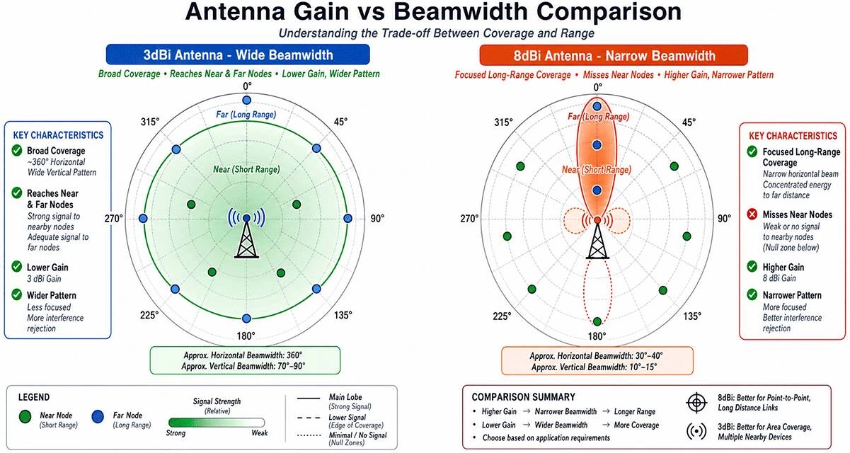
More gain is not always better. While it is tempting to use a very high-gain omnidirectional omni antenna to resolve range limitations, extreme gain alters the vertical beamwidth of the system. According to engineering whitepapers from the LoRa Alliance Regional Parameters Specification, high-gain fiberglass omni antennas (e.g., 8dBi or 10dBi) flatten the RF energy into a narrow, disc-like horizontal pattern.
If your gateway is installed high up on a tower while your IoT nodes or smart water meters are scattered on the ground below, a flattened beamwidth will overshoot the nodes completely, causing severe packet loss in nearby dead zones. For mixed urban environments, a high-quality, medium-gain Fiberglass Omni Outdoor Antenna (3dBi to 5.8dBi) provides an ideal donut-shaped radiation profile, balancing long-distance horizontal reach with reliable vertical coverage.
3. Eradicating Coaxial Cable Loss and Impedance Mismatch
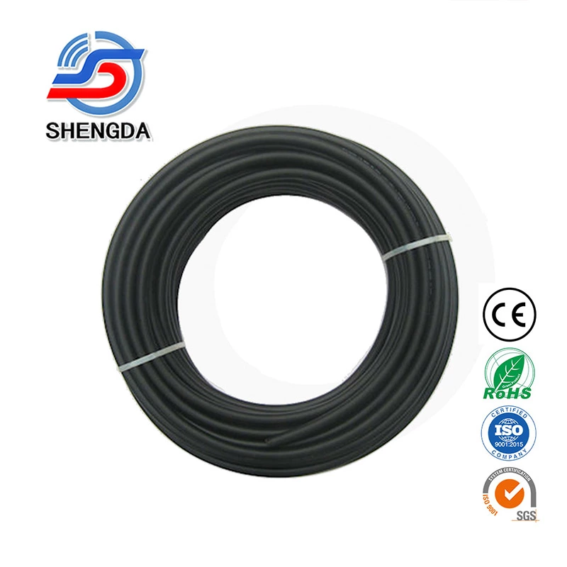
Every decibel (dB) lost in your coaxial feedline directly reduces the gateway’s ability to decode weak, long-range node signals. A common installer error is using thin, high-attenuation cables like RG58 or RG174 for outdoor runs longer than 3 meters.
Standard RF cable attenuation can be precisely calculated using the industry-standard formula:
Attenuation (dB/100ft) = a × √f + b × f
Where f represents the frequency in MHz, and a, b are specific physical constants of the cable material. At sub-GHz frequencies (868MHz / 915MHz), data verified by Times Microwave LMR Systems shows the severe difference in signal degradation across 100 feet (approx. 30 meters) of cabling:
| Cable Type | Attenuation @ 900 MHz (per 100ft) | Efficiency Level for Gateway Deployment |
|---|---|---|
| RG58 Coaxial Cable | 16.5 dB loss | Unacceptable (Losses eat up entire antenna gain) |
| LMR200 Coaxial Cable | 10.5 dB loss | Marginal (Acceptable only for short runs under 2 meters) |
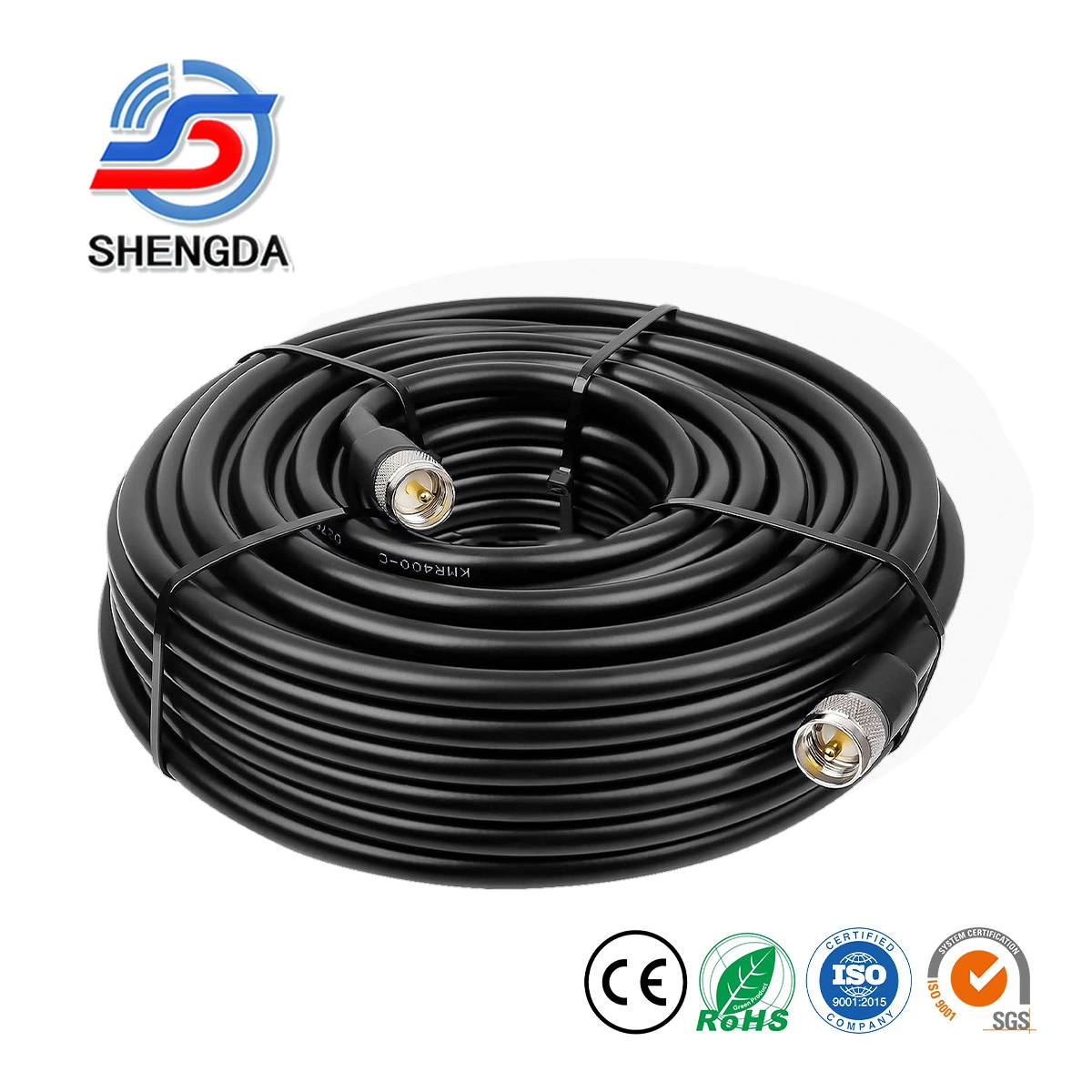
| LMR400 Coaxial Cable | 3.9 dB loss | Excellent (Industry standard for industrial outdoor runs) |
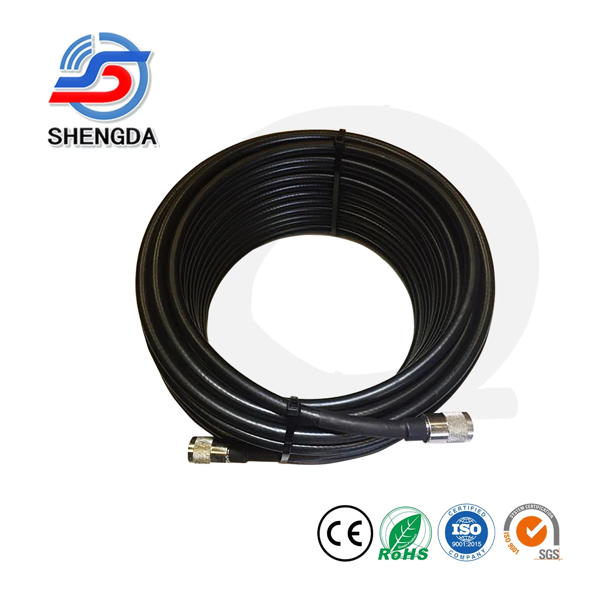
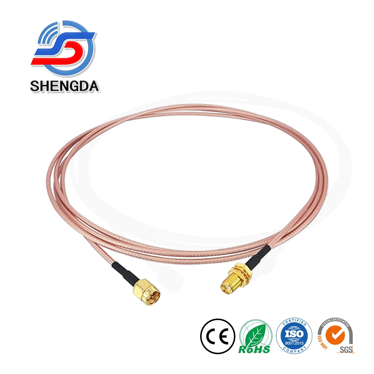
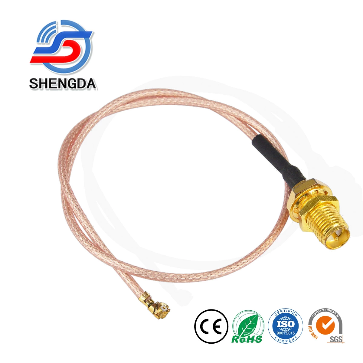
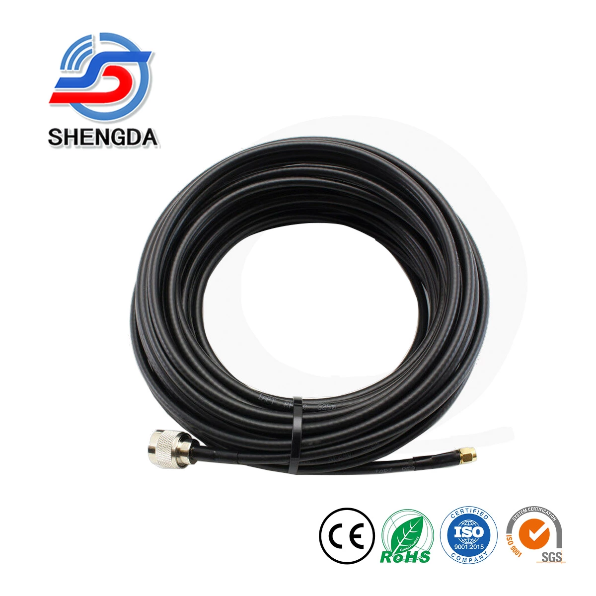
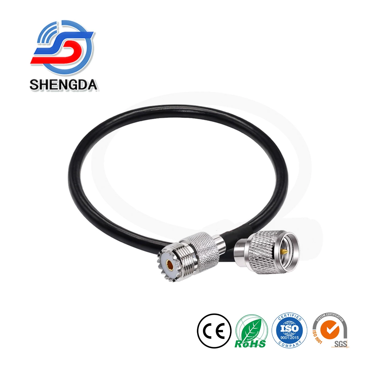
For outdoor links extending beyond 3 meters, transitioning to ultra-low-loss LMR400 Coaxial Assemblies is required. Additionally, ensure all connectors are precision-machined 50-ohm interfaces (such as N-Type or SMA), keeping the Voltage Standing Wave Ratio (VSWR) under ≤ 1.3 to minimize reflection loss back into the gateway receiver.
Conclusion & Factory Custom Solutions
Resolving LoRaWAN packet loss requires meticulous care of physical RF infrastructure. By securing clean line-of-sight elevation, matching antenna gains to your specific topography, and deploying high-grade LMR400 cabling, you can drastically minimize Packet Error Rates and stabilize your edge data streams.
Are you building out a utility monitoring or industrial automation project? As an expert telecom manufacturing base in Fujian, China, we offer end-to-end custom capabilities. Contact our engineering desk today to source specialized fiberglass omni antennas, custom low-loss cable runs, and precise waterproof terminations built exactly to your custom OEM project dimensions.
📋 References & Technical Fact-Checks:
- The Things Network (TTN): "Gateway Placement and Troubleshooting Guidelines" — Structural criteria for Fresnel zone clearance and positioning metrics.
- Semtech Corporation: "LoRaWAN Gateway Hardware Design and Deployment Reference Manual" — Guidelines on physical layer Layer 1 RF link budgets.
- Times Microwave Systems: "Low Loss Coaxial Cable Attenuation and Performance Matrix" — Real-world calculations for RG58, LMR200, and LMR400 attenuation coefficients at 900MHz.
- LoRa Alliance: "LoRaWAN Regional Parameters v1.0.3" — Band specifications and EIRP limits across global sub-GHz networks.