Easily Connect Amateur Radios and Shortwave Radios to a Computer's USB Port
By: RJKORN
I have been using Fldigi for a while now, but I hate long audio cables. Those 3.5mm plugs make quite a lot of crackling noise when you plug the cable in. Besides, I don't want to use an internal sound card.I have looked at commercially available interfaces, but none of them meet my needs. Many different DIY projects are also not quite suitable. What I want is a box with a USB port and a device connector, nothing more. A power plug is not necessary either.
Fldigi (modem) V3.23.21 is a well-known piece of software among amateur radio enthusiasts. It has excellent functions, and for those who enjoy digital communication and CW Morse code, it is presumably no stranger. This software supports Chinese font transmission. It can automatically transmit "CQ CQ CQ" and can also demodulate CW signals for telegraph communication.
This is just as simple as an interface that uses an optocoupled PTT and a transformer isolation device. Both cost less than 20 US dollars.
Step 1: Select an audio dongle
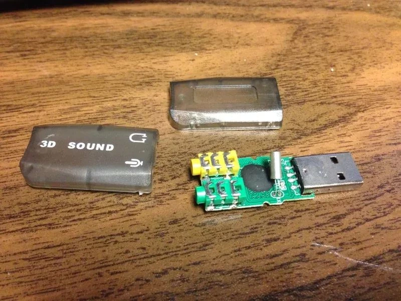
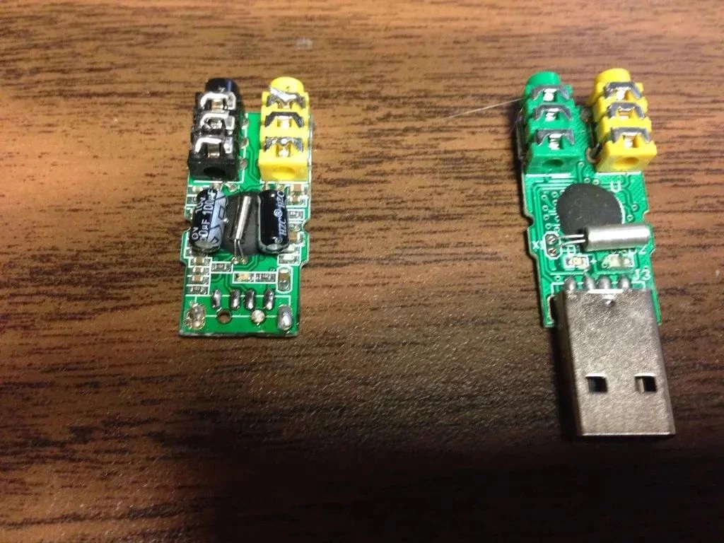
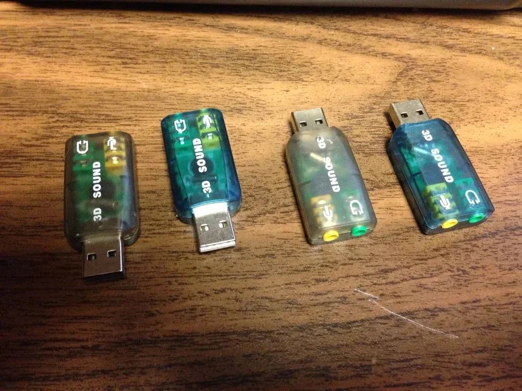
I bought several different USB sound cards from eBay, each costing around $3. We need to pay attention to the products we purchase: those with additional capacitors also have a resistor divider on the audio signal. They only output 100mV, which is not enough to activate the optocoupler. You can see the difference in the picture. Simpler is better. It seems that the bare one outputs almost the full 5V on both the left and right channels.
Step 2: Start Soldering
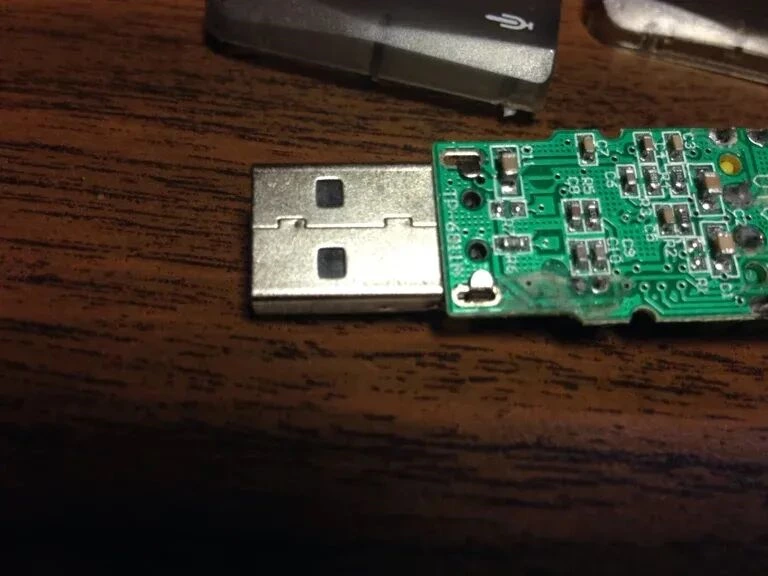
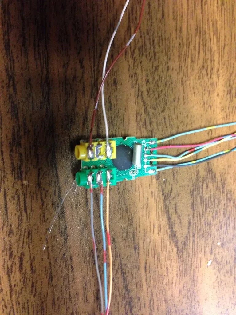
You can keep the USB connector intact and then feed it through the rear panel. I have extra Type-B connectors around, so I don’t solder it. They didn’t even bother to solder the ground tabs at the factory anyway, so if you want to keep the Type-A connector, just desolder those contact tabs.
After removing the USB connector, I soldered the wires to all the USB connections and the top of the 3.5mm jack. Do not disturb the center of the microphone connector, which is not used here.
Step 3: Build the shell
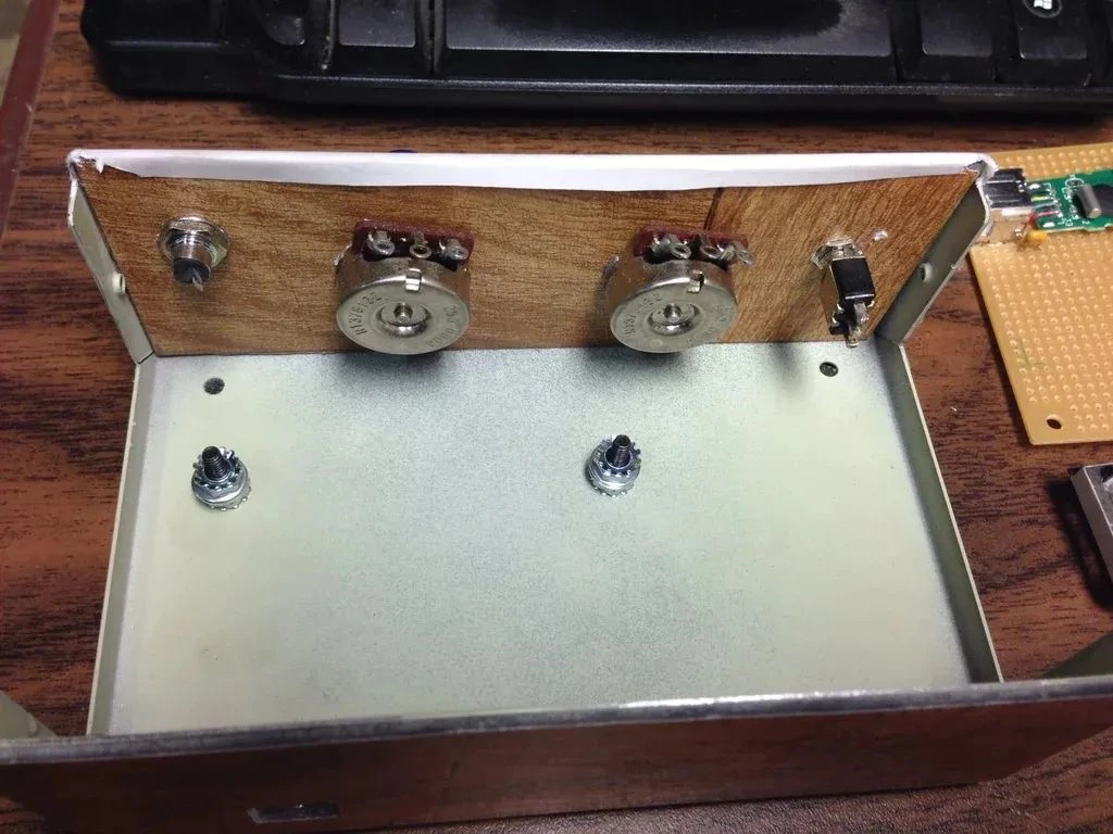
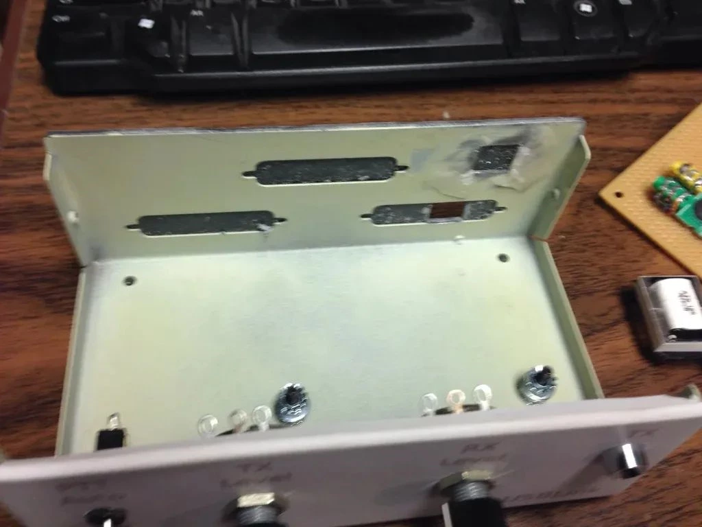
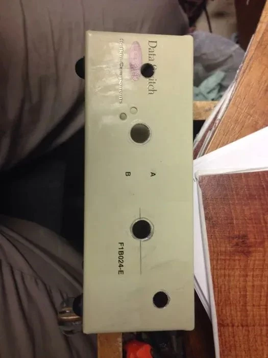
I wanted a good metal case for proper shielding, so I checked the second-hand trading platform and found someone giving away parallel port data switches for free. He was only 2 miles away from me, and there were 3 of them in total.
I just needed to drill a few more holes in the front. I used stripped hardwood floor tiles to make new rear mounts. I drew a quick front panel in Inkscape and printed it on self-adhesive label paper. Several layers of clear adhesive can protect it. I only had satin finish, so it didn’t look as good as the glossy one.
I also used polyurethane on other front panel layouts. It makes the label a bit translucent, so if you’re trying to use a label, flatten it out first before pasting it on. Once dry, it really looks like it’s covered with plexiglass, whose main component is polymethyl methacrylate resin.
I also put a piece of hardwood floor at the back of the front panel to separate the jacks and switches without using a bunch of washers, for a better appearance. Besides, the floor tile is a bit soft, which helps lock the parts in place.
Step 4: Installation
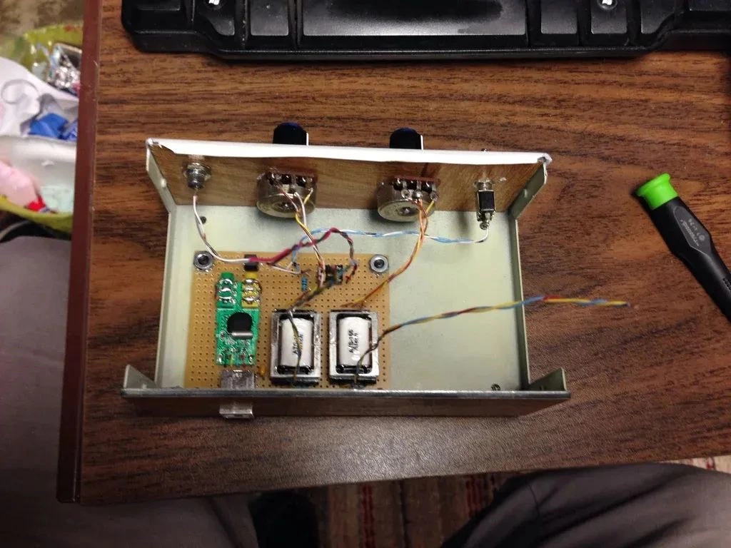
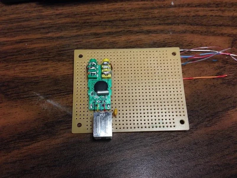
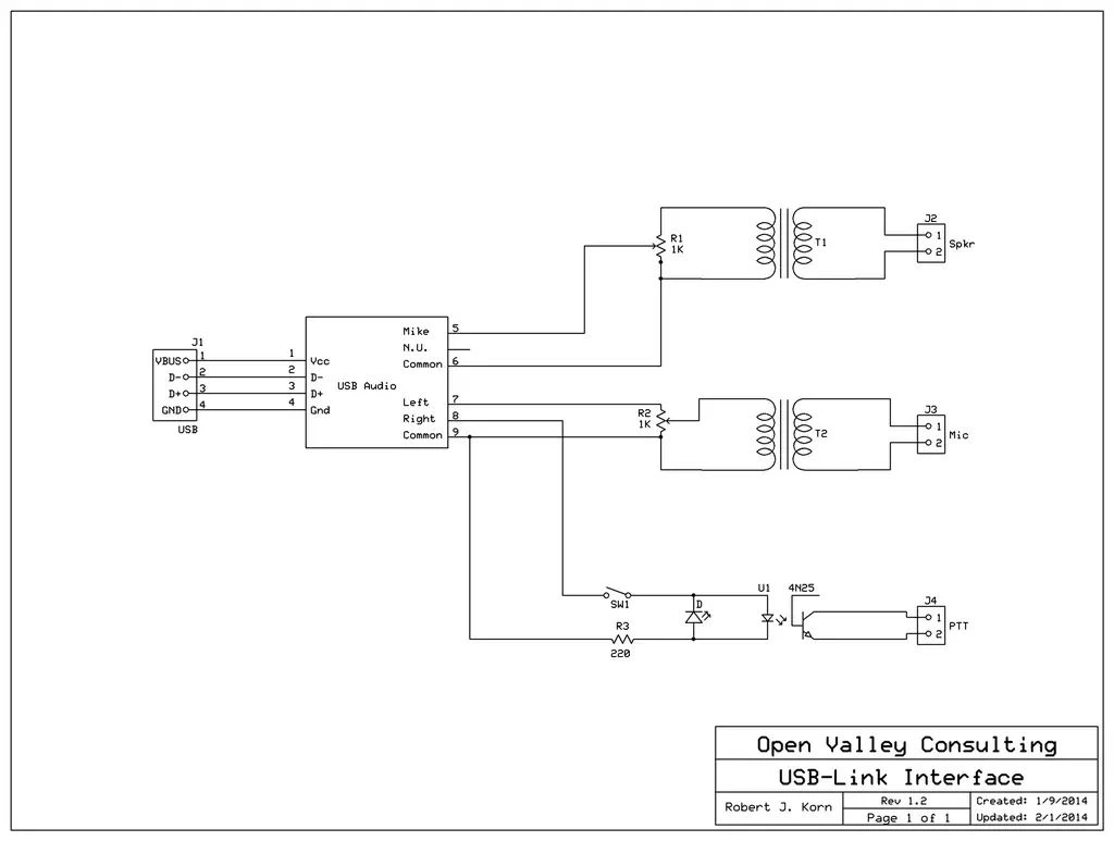
I assembled the components on a small prototype board. The schematic is very simple. I used a socket for the optocoupler, just in case I connect it to a tube device. The schematic shows a 4N35, but I used an IL-5 since I have a lot of these components on hand.
For the radio equipment connector, use a 6-pin DIN or 3 separate connectors as needed. Even a DB-9, RJ45, or similar connector will work.
The transformer is a 1:1 telco transformer. Almost any transformer with an impedance ranging from 100 to 1000 ohms can be used.
