The directivity of a transmitting antenna
The two basic functions of a transmitting antenna not only define the core logic of its energy transmission, but also elevate "directionality" to a key technical dimension—it is not only a direct manifestation of "radiating most of the energy toward the desired direction", but also a core means to balance energy utilization efficiency and communication performance. To gain an in-depth understanding of antenna directionality, it is necessary to analyze it layer by layer from aspects such as its essence, implementation principles, measurement indicators, and practical application value.
1. The Essence of Antenna Directivity: "Directional Distribution" of Energy Radiation
From the perspective of energy transfer, the essence of antenna directivity is the "spatial distribution optimization" of radiated energy. An ideal non-directional antenna (omnidirectional antenna) radiates the energy input by the feeder uniformly to all directions in three-dimensional space, just like a point light source emitting light in all directions. However, in practical applications, "omnidirectional radiation" often means severe energy waste—communication targets usually only exist in specific spatial regions (for example, in communications satellite, the antenna needs to be aligned with the zenith angle where the satellite is located; in base station communications, the antenna needs to cover specific ground cells).
At this point, the core role of directivity becomes prominent: by changing the antenna's structure and electromagnetic field distribution, the originally uniformly dispersed energy is "concentrated" toward the target direction, while reducing energy radiation in non-target directions. This process not only meets the basic functional requirement of "radiating most of the energy toward the required direction" but also indirectly enhances the signal strength in the target direction (due to more concentrated energy) and reduces electromagnetic interference in non-target directions (with less radiated energy), forming the dual advantages of "efficient radiation + anti-interference".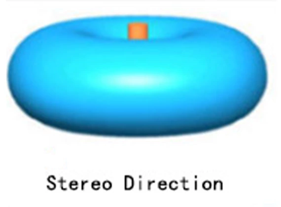
Realization of Directivity: From Structural Design to Electromagnetic Field Regulation
Antenna directivity does not exist naturally; instead, it is achieved through precise structural design and electromagnetic field regulation. The core logic is to "guide the spatial distribution of the electromagnetic field so that energy overlaps and strengthens in the target direction". Common implementation approaches include the following three categories:
- Directivity Optimization Based on Antenna Element Structure
- Directivity of the half-wave dipole: A basic half-wave dipole (such as the telescopic antenna of an FM radio) is not omnidirectional. It radiates omnidirectionally in the plane perpendicular to the dipole axis; however, in the plane parallel to the dipole axis, the radiated energy concentrates in the direction perpendicular to the axis, while the radiation in the directions of the two ends is almost zero, forming an "8"-shaped radiation pattern. This directivity is naturally formed through the current distribution of the dipole itself and the superposition of electromagnetic fields.
- Directivity enhancement of antennas with reflectors: Adding a reflective structure (such as a metal plate or a parabolic reflector) behind the antenna element can "reflect" the energy that would otherwise radiate backward to the front target direction, further increasing the energy density in the front. For instance, in the parabolic antenna of a home satellite TV, the parabolic reflector can convert the spherical waves radiated by the antenna feed (located at the focus of the parabola) into plane waves parallel to the axis, concentrating the energy highly within a narrow beam range in the front. This results in extremely strong directivity, ensuring accurate reception of satellite signals.
- Directivity Superposition Based on Antenna Arrays
When the directivity of a single antenna element fails to meet requirements (e.g., narrower beams or longer radiation distances are needed), multiple identical antenna elements are arranged in a specific pattern (such as linear arrays or planar arrays), and stronger directivity is achieved through "electromagnetic field coherent superposition". Examples include:
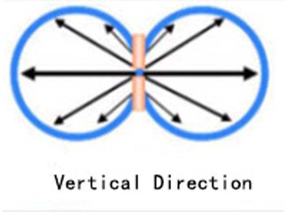
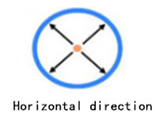
Linear array antennas for base stations: Antennas of mobile communication base stations are usually composed of multiple half-wave dipoles arranged vertically to form a linear array. By adjusting the current amplitude and phase of each dipole, the radiated energy of the array can form a relatively wide beam in the horizontal direction (to cover the entire cell) and a narrow beam in the vertical direction (to reduce upward energy waste and avoid interference with adjacent cells). This directional design of "wide horizontal beam + narrow vertical beam" perfectly meets the base station's needs of "covering ground cells and reducing inter-cell interference".
Dynamic directivity of phased array antennas: More advanced phased array antennas can achieve rapid beam scanning without rotating the physical structure of the antenna (e.g., radar antennas quickly tracking targets, 5G base stations dynamically adjusting beams to align with users) by real-time adjusting the phase of each element in the array. The core advantage of its directivity lies in "flexibility"—it can real-time optimize the energy radiation direction according to changes in the target position, greatly improving the response speed of communication or detection.
Directivity Correlation Based on Operating Frequency
Antenna directivity is also closely related to the operating frequency: with a fixed antenna size, the higher the frequency (the shorter the wavelength), the stronger the directivity usually is. Examples include:
Shortwave antennas (with a wavelength of 10-100 meters) have relatively long wavelengths, and their size is small compared to the wavelength. It is difficult for them to form narrow beams, so their directivity is weak, and they are mostly used for omnidirectional communication.
Microwave antennas (with a wavelength of 1 millimeter - 1 meter) have shorter wavelengths, and their size can match the wavelength or even be much larger than the wavelength. It is easier to design structures with high directivity (such as parabolic microwave antennas) for them. Therefore, they are widely used in scenarios with extremely high directivity requirements, such as satellite communication and point-to-point microwave transmission.
Directionality Measurement Indicators: Quantifying "Energy Concentration Level"
To accurately describe the strength of antenna directionality, the industry has defined three core quantitative indicators, through which it is possible to intuitively determine whether an antenna is suitable for specific application scenarios:
1. Directivity Coefficient (D): The "Theoretical Limit" of Energy Concentration
The directivity coefficient is a fundamental indicator for measuring antenna directionality, defined as "the ratio of the power flux density of the antenna in the maximum radiation direction to that of an ideal omnidirectional antenna in any direction, under the same radiated power". A larger value indicates a stronger ability of the antenna to concentrate energy in the maximum radiation direction. For example, the directivity coefficient of an ideal half-wave dipole is approximately 1.64 (meaning its energy in the maximum direction is 1.64 times stronger than that of an omnidirectional antenna), while the directivity coefficient of a parabolic satellite antenna can exceed 1000, with an energy concentration level far surpassing that of a half-wave dipole.
2. Gain (G): The "Practical Performance" Incorporating Efficiency
The directivity coefficient only considers the "theoretical energy concentration level" and does not account for the antenna's own energy losses (such as metal losses and dielectric losses). In contrast, gain represents the "practical directional performance after accounting for losses" and is defined as "the ratio of the power flux density of the antenna in the maximum radiation direction to that of an ideal omnidirectional antenna, under the same input power".
The relationship between gain and directivity coefficient is expressed as: G = η×D (where η is the antenna efficiency, ranging from 0 to 1). For high-performance antennas with efficiency close to 1 (such as satellite antennas and radar antennas), the values of gain and directivity coefficient are nearly identical. However, for antennas with lower efficiency (such as small civilian antennas), the gain will be significantly lower than the directivity coefficient. In practical antenna selection, users pay more attention to gain. For instance, the gain of a 5G mobile phone antenna needs to reach 3-5 dBi (decibels relative to isotropic), to ensure sufficient signal reception in complex environments.
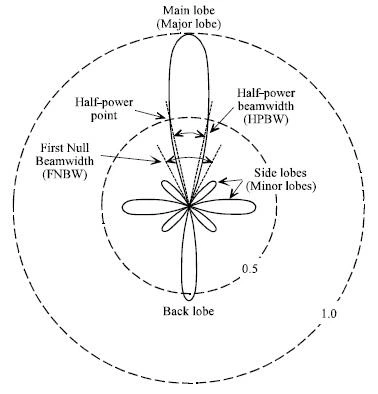
3. Beamwidth: The "Spatial Range" of Directionality
If the directivity coefficient and gain describe "how concentrated the energy is", beamwidth describes "in which spatial range the energy is concentrated". It is usually divided into "Half-Power Beamwidth (HPBW)" and "First-Null Beamwidth (FPBW)":
Half-Power Beamwidth: Refers to the angle between two directions where the antenna's radiated power flux density drops to 1/2 (i.e., a 3 dB power reduction) of that in the maximum direction, and it is the most commonly used indicator. For example, the horizontal half-power beamwidth of a base station antenna is typically 65°-90° (to cover a standard cell), while the horizontal half-power beamwidth of a satellite antenna may be only 0.1°-1° (to accurately align with the satellite).
First-Null Beamwidth: Refers to the angle between two directions where the antenna's radiated power flux density drops to zero. It reflects the "boundary of the energy-concentrated area" and can be used to judge the antenna's ability to suppress interference in non-target directions. A narrower first-null beamwidth indicates less radiation in non-target directions and lower interference.
Practical Applications of Directivity: "Customized Requirements" for Different Scenarios
The design of antenna directivity is not about "the stronger the better"; instead, it requires "customized adjustment" based on the needs of specific application scenarios. Below are the directivity application logics for three typical scenarios:
1. Wide Coverage Scenarios: Moderate Directivity to Balance Coverage Range and Signal Strength
In scenarios that require covering large areas (such as FM broadcasting, medium-wave communication, and early 2G base stations), antennas need to have "moderate directivity"—they should not disperse energy too much like omnidirectional antennas, nor have too small a coverage range like narrow-beam antennas. For example, FM broadcasting antennas usually adopt a design of "omnidirectional vertical polarization + moderate concentration in the horizontal direction": the vertical direction is omnidirectional to ensure that receiving devices at different heights (such as ground radios and car radios) can all receive signals; in the horizontal direction, array design is used to concentrate energy in the broadcast coverage area (e.g., within a 20-kilometer radius of a city), avoiding energy waste in uninhabited areas.
2. Long-Distance Point-to-Point Scenarios: High Directivity to Maximize Energy Utilization
In long-distance point-to-point scenarios such as satellite communication, microwave relay, and radar detection, antennas need to have "extremely high directivity" and concentrate energy in a very small spatial range through narrow beams to overcome energy attenuation during long-distance transmission. Examples include:
Satellite ground station antennas: Their half-power beamwidth is usually only 0.5°-2°, and the directivity coefficient exceeds 1000. They can accurately align energy with geosynchronous satellites 36,000 kilometers above the ground, ensuring that signals can travel across long distances to reach the satellites while avoiding interference with other satellites.
Military radar antennas: Narrow beams (half-power beamwidth can be less than 0.1°) and rapid scanning are achieved through phased array technology. This not only enables long-distance target detection (concentrated energy results in a long detection range) but also allows for precise target tracking (narrow beams lead to high positioning accuracy).
3. Multi-User Communication Scenarios: Dynamic Directivity to Adapt to Changes in User Positions
In multi-user scenarios such as 5G communication and the Internet of Things (IoT), user positions change dynamically, making antennas with fixed directivity difficult to meet requirements. Therefore, "dynamic directivity" has become a core technology—by adjusting the beam direction of phased array antennas in real time, energy is accurately allocated to each user, realizing "beams following users". For example:
Massive MIMO antennas of 5G base stations: Composed of dozens or even hundreds of antenna elements arranged in an array, they can generate multiple narrow beams simultaneously, each aligned with users at different positions. When users move, the base station adjusts the beam direction and parameters in real time to ensure that users are always in the energy-concentrated area. This not only improves users' communication rates (due to concentrated energy) but also reduces interference between users (as beams do not overlap with each other).