Antenna Polarization Loss
Ⅰ.Core Logic and Practical Significance of Polarization Matching
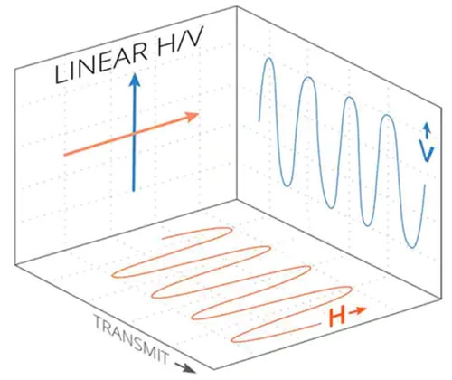
As a key characteristic of electromagnetic waves, polarization directly determines the "adaptation degree" between the receiving antenna and the incoming wave signal — it is analogous to two keys of different shapes; only when the "tooth shape" (polarization direction) matches completely can the signal transmission channel be efficiently "opened". The principle that "consistent polarization direction enables efficient reception, while inconsistency leads to loss" essentially stems from the coupling law between the electric field direction of electromagnetic waves and the current direction of the antenna element: when the polarization characteristics of the antenna are completely consistent with the polarization direction of the incoming wave, the electric field can drive the antenna element to generate an induced current to the greatest extent, realizing efficient signal conversion; however, once the directions deviate, the coupling efficiency decreases as the deviation angle increases, a process known as "polarization mismatch" in communication systems.
This mismatch does not exist merely in theory, but runs through various wireless communication scenarios. For example, in civil CB radio communication, most vehicle-mounted antennas adopt a vertical polarization design (because vertically polarized waves are less affected by obstacles when propagating on the ground, making them suitable for short-to-medium distance mobile communication). If a user mistakenly selects a horizontally polarized antenna, even if the antenna gain and frequency band adaptation meet the standards, the orthogonal polarization directions will cause significant signal attenuation, manifested as increased call noise, shortened communication distance, and even signal interruption in complex terrain — this is the direct impact of polarization loss on actual communication experience.
(Image credit: Mimosa Networks, Inc.)
II. Quantitative Analysis and Technical Indicators of Polarization Loss
Phenomena such as "only half the energy can be obtained when cross-receiving linear polarization and circular polarization" and "signal leakage in dual-polarized antennas" can be further quantified through specific technical indicators, helping to more intuitively understand the degree of polarization mismatch. Taking dual-polarized antennas as an example, the "cross-polarization ratio (XPR)" is commonly used in the industry to measure the polarization isolation effect, and its calculation formula is: Cross-Polarization Ratio (dB) = 10lg (Input Power of Main Polarized Antenna / Leakage Power of Cross-Polarized Antenna).
Case Study: The input power of the vertically polarized antenna is 10W (i.e., 10,000mW), and the leakage power of the horizontally polarized antenna is 10mW. Substituting into the formula, the cross-polarization ratio is calculated as 10lg (10,000mW / 10mW) = 10lg1000 = 30dB. This 30dB indicator represents a high level of polarization isolation in practical applications (the cross-polarization ratio of ordinary civil dual-polarized antennas usually ranges from 25dB to 35dB), which means that the leakage ratio of vertically polarized signals to the horizontal polarization direction is only 0.1% (10mW / 10,000mW). Although it does not reach "ideal complete polarization isolation", it can already meet the needs of most short-to-medium distance communications — for example, in fleet dispatching scenarios, such slight signal leakage will not cause obvious interference to the main communication link, and may only be amplified into weak background noise in extremely complex electromagnetic environments (such as the presence of strong interference sources nearby).
When the cross-polarization ratio indicator is low (for example, some low-cost dual-polarized antennas can only reach 20dB), the leakage power ratio will rise to 1% (when the input is 10W, the leakage power is 100mW). In this case, the phenomenon of "frequency crosstalk" may occur: for instance, the voice signal transmitted through the vertical polarization channel will generate recognizable noise in the horizontal polarization channel, affecting clarity communication. This also explains why professional communication equipment (such as dual-polarized antennas for emergency communication vehicles) takes the cross-polarization ratio as one of the core performance parameters. By optimizing the antenna element structure and adoption a feeding network with higher isolation, polarization leakage is minimized as much as possible to reduce signal interference.
(Image credit: Electronics-Notes)
III. The Gap Between Ideal and Realistic Polarization Isolation
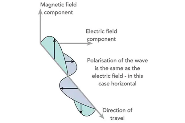
"Ideal complete polarization isolation does not exist", which stems from the physical characteristics of electromagnetic wave propagation and the process limitations of antenna manufacturing. From a physical perspective, any electromagnetic wave will undergo "polarization rotation" during propagation due to factors such as atmospheric refraction, ground reflection, and obstacle scattering — for example, when a vertically polarized wave passes through a densely built-up area, affected by multiple reflections on the surface of buildings, part of the signal will be converted into tilted polarization (such as +30° or -20° polarization), resulting in deviations in the originally "pure" polarization direction. From the perspective of antenna manufacturing, even if the polarization characteristics are strictly followed during design, minor deformations of the oscillator and slight deviations of the feed point in actual production may cause the antenna to have the problem of "impure polarization", making the main polarization signal mixed with a small amount of cross-polarization components.
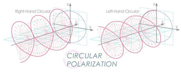
This "non-ideal isolation" has a more significant impact in communication systems sharing multiple polarizations. For example, in radio and television transmission, some satellite antennas adopt a circular polarization design (such as right-hand circular polarization) to cope with changes in polarization direction caused by fine adjustments of satellite attitude. However, even so, a small amount of left-hand circular polarization signals will still be mixed in — but due to the high signal strength of satellite communication, this slight leakage can usually be suppressed by the signal processing circuit at the receiving end (such as a polarization filtering module), and will not have a significant impact on image quality and sound quality. In scenarios with extremely high requirements for signal sensitivity (such as deep-space exploration and military communication), engineers need to use "polarization tracking technology" to adjust the antenna polarization direction in real time, compensate for the polarization rotation during propagation, narrow the gap with ideal polarization isolation as much as possible, and ensure the stable reception of key signals.
(Image credit: JEM Engineering)
IV. Practical Countermeasures for Polarization Loss
In the face of unavoidable polarization loss, targeted measures need to be taken to reduce its impact during the design of practical communication systems and the selection of equipment:
1.Prioritize the selection of antennas with matching polarization: After clarifying the polarization requirements of the communication scenario, prioritize the selection of antennas with consistent polarization characteristics. For example, in CB vehicle-mounted radio communication, if most users use vertically polarized antennas, horizontally polarized antennas should be avoided; in satellite communication, if the satellite transmits right-hand circularly polarized signals, a right-hand circularly polarized satellite antenna should be matched to reduce polarization mismatch from the source.
2.Optimize signal reception using polarization technology: For scenarios with complex signal environments (such as dense urban areas and mountainous areas), a "polarization diversity reception" scheme can be adopted — that is, two types of antennas with orthogonal polarization (e.g., vertically polarized + horizontal diversityly polarized antennas) are deployed simultaneously. The receiving end uses signal processing algorithms to real-time select signals with smaller polarization loss or combine the two signals, thereby offsetting the attenuation caused by polarization mismatch. This technology is widely used in 4G/5G base stations and professional emergency communication equipment, and can effectively improve the stability of signal reception.
3.Evaluate communication risks through index calculation: Before building a communication system, the possible polarization loss can be calculated based on parameters such as the cross-polarization ratio of the antenna and the stability of the incoming wave polarization. power is approximately 63.2mW. If the receiving end has low sensitivity (e.g., only able to detect signals above 100mW), this leakage will not cause interference; however, if the receiving end has extremely high sensitivity (e.g., able to detect signals above 10mW), additional isolation circuits need to be added to prevent the leaked signal from affecting the main channel.
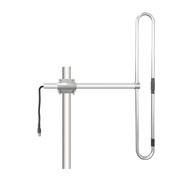
For applications requiring vertical polarization, a dipole antenna can be mounted accordingly to catch up with the antenna.
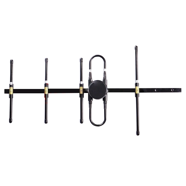
The widely used dipole antennas (planar or folded type) are horizontally polarized in their "normal" installation orientation, and are often rotated by 90 degrees to exhibit vertical polarization when needed or to support the preferred polarization mode.
V. Polarization Leakage and Application Expansion of Dual-Polarized Antennas
The case of dual-polarized antennas reveals the core contradiction of the "polarization multiplexing" technology — it is necessary to share the same antenna through two types of polarization (to save installation space and reduce costs) while minimizing signal interference between polarizations as much as possible. Such antennas are widely used in scenarios that require simultaneous transmission of two independent signals. For example, in the dispatching system of a logistics fleet, the vertical polarization channel can be used to transmit vehicle positioning data, and the horizontal polarization channel to transmit voice commands, realizing "one antenna for multiple uses".
However, in practical applications, it is necessary to balance "multiplexing efficiency" and "isolation" according to scenario requirements: if the scenario has high requirements for signal independence (such as military secure communication), high-performance dual-polarized antennas with a cross-polarization ratio of more than 40dB should be selected to control the leakage power ratio below 0.01% and avoid data leakage; while in the temporary networking of civil CB radios, antennas with a cross-polarization ratio of about 30dB can already meet the needs, with lower cost and more convenient installation. In addition, the polarization leakage of dual-polarized antennas is also affected by the installation environment — for example, when there are metal obstacles near the antenna (such as vehicle exhaust pipes, roof racks), the reflection of electromagnetic waves by the obstacles may change the polar characterization of the antenna, leading to a decrease in the cross-polarization ratio. Therefore, metal shielding should be avoided during installation to ensure the stable performance of the antenna's polarization characteristics.